Register now for better personalized quote!

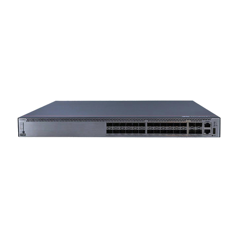
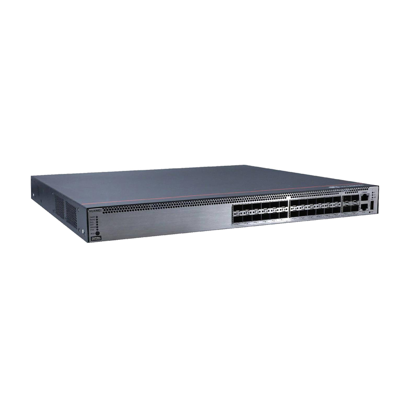
| Detail: | S5731-H24HB4XZ (20*Hybrid GE SFP ports, 4*Hybrid 10GE SFP+ ports, 4*10GE SFP+ ports, 1*expansion slot, PoE++, without power module) |
| Model: | S5731-H24HB4XZ (02354QXD 02354QXD-001) |
| Condition: | Factory Sealed New |
| Related: | |
| Warranty: |
 3 Years-Warranty
 100% Money-back
 Free After-Sales Service
|
| Shipping: |
Air Shipping to
United States
, Most Customers Receive during 5-7 Days
?
If you finish the payment today,
your order will arrive within the estimated delivery time. |
| Ships to:
15
|
2-7 Days
US$
|
| Payment: |
More
|
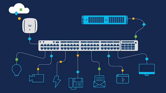
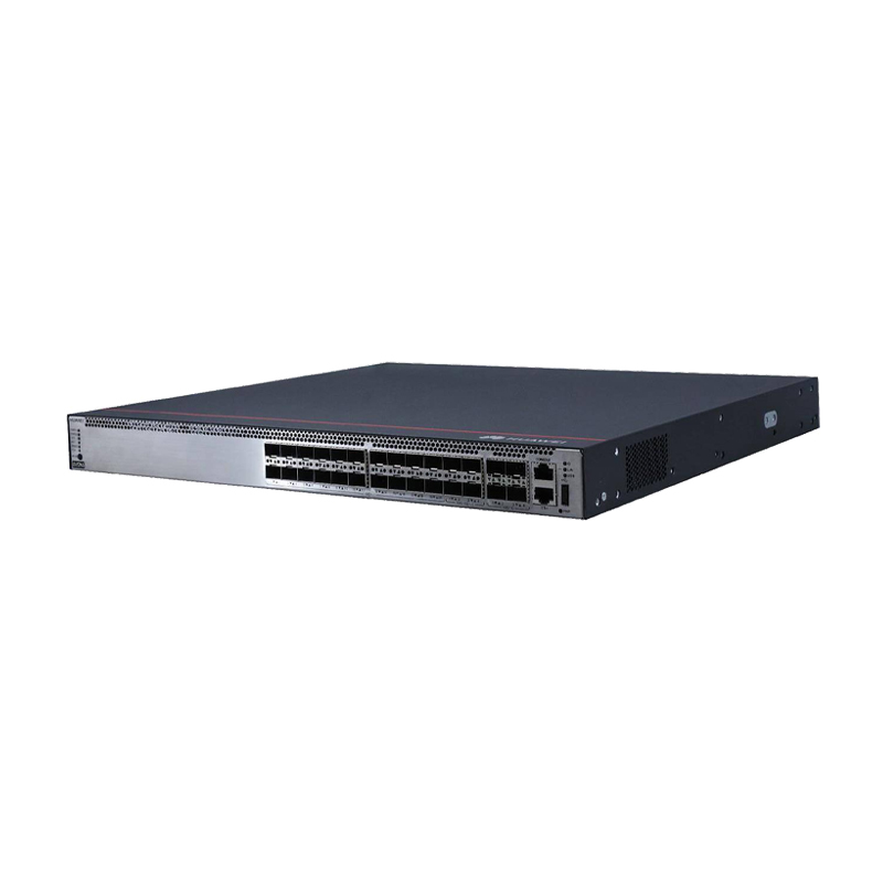
The CloudEngine S5731-H series switches are the next-generation intelligent gigabit fixed switches developed by Huawei. The CloudEngine S5731-H builds on Huawei's unified Versatile Routing Platform (VRP) and boasts various IDN features. For example, the integrated wireless AC capabilities can manage up to 1,024 wireless APs; the free mobility feature ensures consistent user experience; the VXLAN functionality implements network virtualization; and built-in security probes support abnormal traffic detection, threat analysis even in encrypted traffic, and network-wide threat deception. With these merits, the CloudEngine S5731-H can function as core switches for small-sized campus networks and branches of medium- and large-sized campus networks, and also work as access switches for Metropolitan Area Network.
Model | S5731-H24HB4XZ |
Part Number | 02354QXD, 02354QXD-001 |
Description | S5731-H24HB4XZ (20*Hybrid GE SFP ports, 4*Hybrid 10GE SFP+ ports, 4*10GE SFP+ ports, 1*expansion slot, PoE++, without power module) |
Dimensions without packaging (H x W x D) [mm(in.)] | Basic dimensions (excluding the parts protruding from the body): 43.6 mm x 442.0 mm x 420.0 mm (1.72 in. x 17.4 in. x 16.54 in.) Maximum dimensions (the depth is the distance from ports on the front panel to the parts protruding from the rear panel): 43.6 mm x 442.0 mm x 448.0 mm (1.72 in. x 17.4 in. x 17.64 in.) |
Weight with packaging [kg(lb)] | 7.5 kg (16.53 lb) |
Typical power consumption [W] | 87 W |
Maximum power consumption [W] | Without PoE: 127 W (without cards) Full PoE load: 1927 W (PoE: 1768 W, without cards) |
Memory | 2 GB |
Flash memory | 1 GB in total. To view the available flash memory size, run the display version command. |
PoE | Supported |


Note:
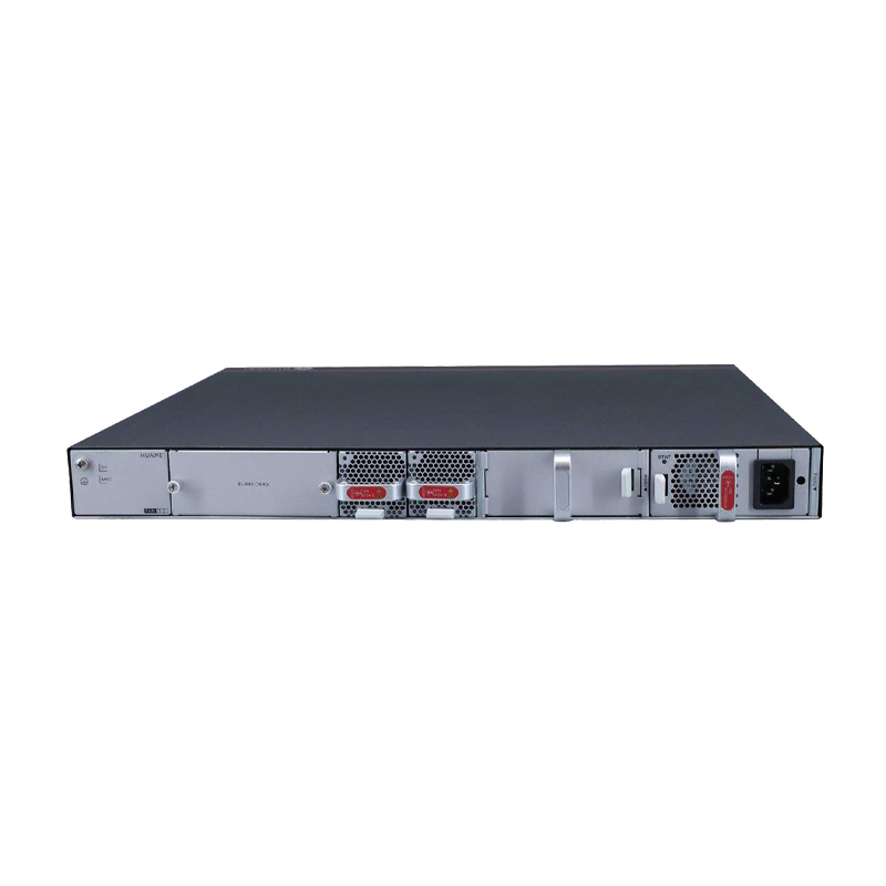
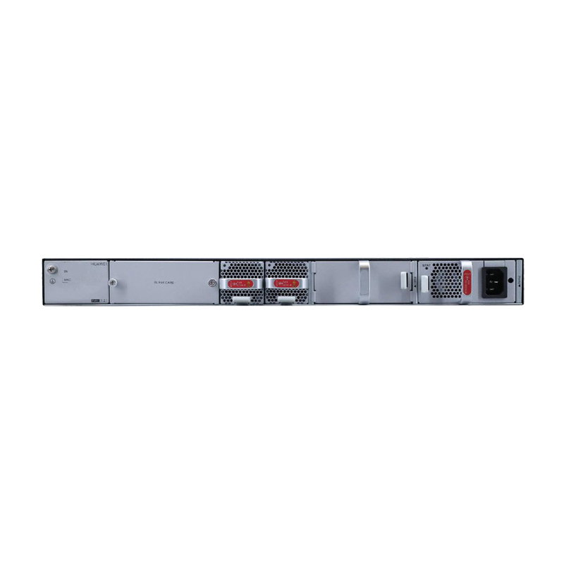
(1) | Twenty 100/1000BASE-X hybrid optical-electrical ports (supporting PoE++) | (8) | Ground screw |
(2) | Four 10GE SFP+ hybrid optical-electrical ports (supporting PoE++) | (9) | Rear card slot |
(3) | Four 10GE SFP+ optical ports | (10) | Fan module slot 1 |
(4) | One ETH management port | (11) | Fan module slot 2 |
(5) | One console port | (12) | Power module slot 1 |
(6) | One USB port | (13) | Power module slot 2 |
(7) | One PNP button |

No. | Indicator | Name | Color | Status | Description |
1 | PWR1 | Power module indicator | - | Off | No power module is available in power module slot 1, or the switch has only one power module but the power module does not work normally. |
Green | Steady on | A power module is installed in power module slot 1 and is working normally. | |||
Yellow | Steady on | The switch has two power modules installed. Any of the following situations occurs in power module slot 1: ● A power module is available in this slot but it is not connected to a power source. ● The power module in this slot has failed. | |||
2 | PWR2 | Power module indicator | - | Off | No power module is available in power module slot 2, or the switch has only one power module but the power module does not work normally. |
Green | Steady on | A power module is installed in power module slot 2 and is working normally. | |||
Yellow | Steady on | The switch has two power modules installed. Any of the following situations occurs in power module slot 2: ● A power module is available in this slot but it is not connected to a power source. ● The power module in this slot has failed. | |||
3 | SYS | System status indicator | - | Off | The system is not running. |
Green | Fast blinking | The system is starting. | |||
Green | Steady on | During the system startup preparation phase, the SYS indicator is steady green, which lasts for a maximum of 30 seconds. | |||
Green | Slow blinking | The system is running normally. | |||
Red | Steady on | The system does not work normally after registration, or a fan alarm or a temperature alarm has been generated. | |||
4 | MST | Stack indicator | - | Off | ● If you are not changing the indicator mode (default): The switch is a standby or slave switch in a stack or the stacking function is not enabled on the switch. ● If you are changing the indicator mode: The stack mode is not selected. |
Green | Steady on | The stack mode is selected. The switch is a standby or slave switch in a stack, and the service port indicators show the stack ID of the switch. | |||
Green | Blinking | ● If you are not changing the indicator mode (default): The switch is the master switch in a stack or a standalone switch with the stacking function enabled. ● If you are changing the indicator mode: The stack mode is selected. The switch is the master switch in a stack or a standalone switch, and the service port indicators show the stack ID of the master switch. After 45 seconds, the service port indicators automatically restore to the status mode. | |||
5 | SPEED | Speed indicator | - | Off | The speed mode is not selected. |
Green | Steady on | The speed mode is selected, and service port indicators show the speed of each port. | |||
6 | PoE | PoE indicator | - | Off | The PoE mode is not selected. |
Green | Steady on | The PoE mode is selected, and service port indicators show the PoE status of each port. | |||
7 | MODE | Mode switch button | - | - | ● When you press this button once, the service port indicators change to the stack mode and show the stack ID of the local switch. ● When you press this button a second time, the service port indicators change to the speed mode and show the speed of each service port. ● When you press this button a third time, the service port indicators change to the PoE mode and show the PoE status of each service port. ● When you press this button a fourth time, the service port indicators restore to the default mode and show the connection status and link activity of each service port. If you do not press the MODE button within 45 seconds, the service port indicators restore to the default mode. In this case, the SPEED and PoE indicators are off. NOTE: Hold down the mode switch button for 6s and release it to start the web initial login mode. Either of the following situations will occur: ● If the switch has no configuration file, the system attempts to enter the web initial login mode. In this mode, the status of mode indicators is as follows: ● If the system enters the web initial login mode successfully, all mode indicators turn green and stay on for a maximum of 10 minutes. ● If the system fails to enter the initial login mode, all mode indicators fast blink for 10 seconds and then restore the default status. ● If the switch has a configuration file, the system cannot enter the web initial login mode. In this case, all mode indicators fast blink for 10s, and then return to the default states. |
8 | - | Hybrid optical-electrical port indicator | Arrowheads show the positions of ports. A down arrowhead indicates a port at the bottom, and an up arrowhead indicates a port at the top. | Meanings of service port indicators vary in different modes. | |
10GE optical port indicator | Each optical port has two single-color indicators. The one on the left is the ACT indicator (yellow), and the one on the right is the LINK indicator (green). Arrowheads show the positions of ports. A down arrowhead indicates a port at the bottom, and an up arrowhead indicates a port at the top. | ||||
9 | ID | ID indicator | - | Off | The ID indicator is not used (default state). |
Blue | Steady on | The indicator identifies the switch to maintain. The ID indicator can be turned on or off remotely to help field engineers find the switch to maintain. | |||
10 | L/A | ETH port indicator | - | Off | The ETH port is not connected. |
Green | Steady on | The ETH port is connected. | |||
Green | Blinking | The ETH port is sending or receiving data. | |||
11 | USB | USB-based deployment indicator | - | Off | ● No USB flash drive is connected to the switch. ● The USB port is damaged. ● The indicator is damaged. ● The USB flash drive does not have any configuration file and cannot be used for deployment. ● The switch has been upgraded using the USB flash drive and is restarting. |
Green | Steady on | A USB-based deployment has been completed. | |||
Green | Blinking | The system is reading data from a USB flash drive. | |||
Yellow | Steady on | The switch has copied all the required files and completed the file check. The USB flash drive can be removed from the switch. | |||
Red | Blinking | An error has occurred when the system is executing the configuration file or reading data from the USB flash drive. | |||
Do you have any question about the S5731-H24HB4XZ (02354QXD 02354QXD-001)?
Contact us now via [email protected].
S5731-H24HB4XZ Specification | |
Model | S5731-H24HB4XZ |
Part Number | 02354QXD, 02354QXD-001 |
Description | S5731-H24HB4XZ (20*Hybrid GE SFP ports, 4*Hybrid 10GE SFP+ ports, 4*10GE SFP+ ports, 1*expansion slot, PoE++, without power module) |
Dimensions without packaging (H x W x D) [mm(in.)] | Basic dimensions (excluding the parts protruding from the body): 43.6 mm x 442.0 mm x 420.0 mm (1.72 in. x 17.4 in. x 16.54 in.) Maximum dimensions (the depth is the distance from ports on the front panel to the parts protruding from the rear panel): 43.6 mm x 442.0 mm x 448.0 mm (1.72 in. x 17.4 in. x 17.64 in.) |
Dimensions with packaging (H x W x D) [mm(in.)] | 185 mm x 650 mm x 550 mm (7.28 in. x 25.59 in. x 21.65 in.) |
Chassis height [U] | 1 U |
Weight without packaging [kg(lb)] | 5.7 kg (12.57 lb) |
Weight with packaging [kg(lb)] | 7.5 kg (16.53 lb) |
Typical power consumption [W] | 87 W |
Typical heat dissipation [BTU/hour] | 296.85 BTU/hour |
Maximum power consumption [W] | Without PoE: 127 W (without cards) Full PoE load: 1927 W (PoE: 1768 W, without cards) |
Maximum heat dissipation [BTU/hour] | Without PoE: 433.34 (without cards) Full PoE load: 6575.12 (without cards) |
Static power consumption [W] | 66 W |
MTBF [years] | 53.82 years |
MTTR [hours] | 2 hours |
Availability | > 0.99999 |
Noise at normal temperature (acoustic power) [dB(A)] | Dual-AC 600 W, 70% load: 57.77 dBA Dual-AC 1000 W, 70% load: 63.78 dBA Dual-DC 1000 W, 70% load: 62.38 dBA Dual-AC 600 W, 100% load: 63.78 dBA Dual-AC 1000 W, 100% load: 68.07 dBA Dual-DC 1000 W, 100% load: 66.26 dBA |
Number of card slots | 1 |
Number of power slots | 2 |
Number of fans modules | 2 |
Redundant power supply | 1+1 Pluggable AC and DC power modules can be used together in the same switch, but power modules that use natural heat dissipation and power modules that use air cooling cannot be used together. |
Long-term operating temperature [°C(°F)] | –5°C to +45°C (23°F to 113°F) at an altitude of 0 to 1800 m (0 to 5905.51 ft.) |
Short-term operating temperature [°C(°F)] | -5°C to +50°C (23°F to 122°F) at an altitude of 0-1800 m (0-5905.44 ft.) |
Restriction on the operating temperature variation rate [°C(°F)] | When the altitude is 1800–5000 m (5906–16404 ft.), the highest operating temperature reduces by 1°C (1.8°F) every time the altitude increases by 220 m (722 ft.). The device can work for a short period of time when the operating temperature is beyond the normal range, but the following conditions must be met: The operating temperature can exceed 45°C (113°F) for a maximum of 96 consecutive hours in a year. The total time when the operating temperature exceeds 45°C (113°F) in a year is less than or equal to 360 hours. The number of times the operating temperature exceeds 45°C (113°F) is less than or equal to 15 in one year. If any of the preceding conditions is not met, the device may be damaged or an unknown error may occur. Devices cannot start when the temperature is lower than 0°C (32°F). The maximum transmission distance of an optical module used for short-term operation cannot exceed 10 km. |
Storage temperature [°C(°F)] | –40°C to +70°C (–40°F to +158°F) |
Long-term operating relative humidity [RH] | 5% RH to 95% RH (non-condensing) |
Long-term operating altitude [m(ft.)] | 0–5000 m (0–16404 ft.) |
Storage altitude [m(ft.)] | 0-5000 m (0-16404 ft.) |
Power supply mode | Pluggable power supply |
Rated input voltage [V] | AC input: 100 V AC to 240 V AC; 50/60 Hz High-voltage DC input: 240 V DC DC input: –48 V DC to –60 V DC |
Input voltage range [V] | AC input: 90 V AC to 290 V AC; 45–65 Hz High-voltage DC input: 190 V DC to 290 V DC DC input: -38.4 V DC to -72 V DC |
Maximum input current [A] | The current specifications are related to the pluggable power module. For details, see Pluggable Power Modules. |
Memory | 2 GB |
Flash memory | 1 GB in total. To view the available flash memory size, run the display version command. |
Console port | RJ45 |
Eth Management port | RJ45 |
USB | Supported |
RTC | Supported |
RPS input | Not supported |
Service port surge protection [kV] | - |
Power supply surge protection [kV] | Configured with AC power modules: ±6 kV in differential mode and ±6 kV in common mode Configured with DC power modules: ±2 kV in differential mode and ±4 kV in common mode |
Ingress protection level (dustproof/waterproof) | IP20 |
Types of fans | Pluggable |
Heat dissipation mode | Air cooling for heat dissipation, intelligent fan speed adjustment |
Airflow direction | Air intake from left, front, and right and air exhaust from rear |
PoE | Supported |
Certification | EMC certification (The EMC radiated emission complies with standards requirements, although it may vary according to installation of optical modules or copper modules.) Safety certification Manufacturing certification |
What is Guaranteed.
After receiving your order, take a full month to try it out. If you find quality is not good , we'll take it back and refund your money. Your complete satisfaction is GUARANTEED or your money back. That's guaranteed.
After your order items which are available. We will use most fast delivery way to global countries. Normally we will ship out cargos during 3 -5 days. And international delivery will take about 3- 10 days according to your location.
Service Never Ends.
Hardwares Warrany Time:
Original New Sealed Hardware: 3 Years
Refurbished/Used Original Devices: 1 Year
After warranty time, you also can contact us to return back for repair service. Everything you purchase from HI-NETWORK.COM. We will offer lifetime online service support for your any possible questions.
Register Email now for Weekly Promotion Stock
100% free, Unsubscribe any time!
Add 1: Room 605 6/F FA YUEN Commercial Building, 75-77 FA YUEN Street, Mongkok KL, HongKong Add 2: Room 405, Building E, MeiDu Building, Gong Shu District, Hangzhou City, Zhejiang Province, China
Whatsapp/Tel: +8618057156223 Tel: 0086 571 86729517 Tel in HK: 00852 66181601
Email: [email protected]
 English
 Pусский
 Français
 Español
 Português