Register now for better personalized quote!

| Detail: | Cisco AIR-ANT2547VG-N 2.4 GHz 2 dBi/5 GHz 4 dBi Dipole Ant., RP-TNC |
| Model: | AIR-ANT2547VG-N |
| Condition: | Factory Sealed New, In stock |
| Related: | |
| Warranty: |
 1 Year-Warranty
 100% Money-back
 Free After-Sales Service
|
| Shipping: |
Air Shipping to
United States
, Most Customers Receive during 5-7 Days
?
If you finish the payment today,
your order will arrive within the estimated delivery time. |
| Ships to:
0.2
|
2-7 Days
US$
|
| Payment: |
More
|
(Note: Cisco discount and Stock always changed, we will try most effort to follow it but can not ensure every web was changed accordingly. So Our Products Service will contact you after order if meet such special condition.)
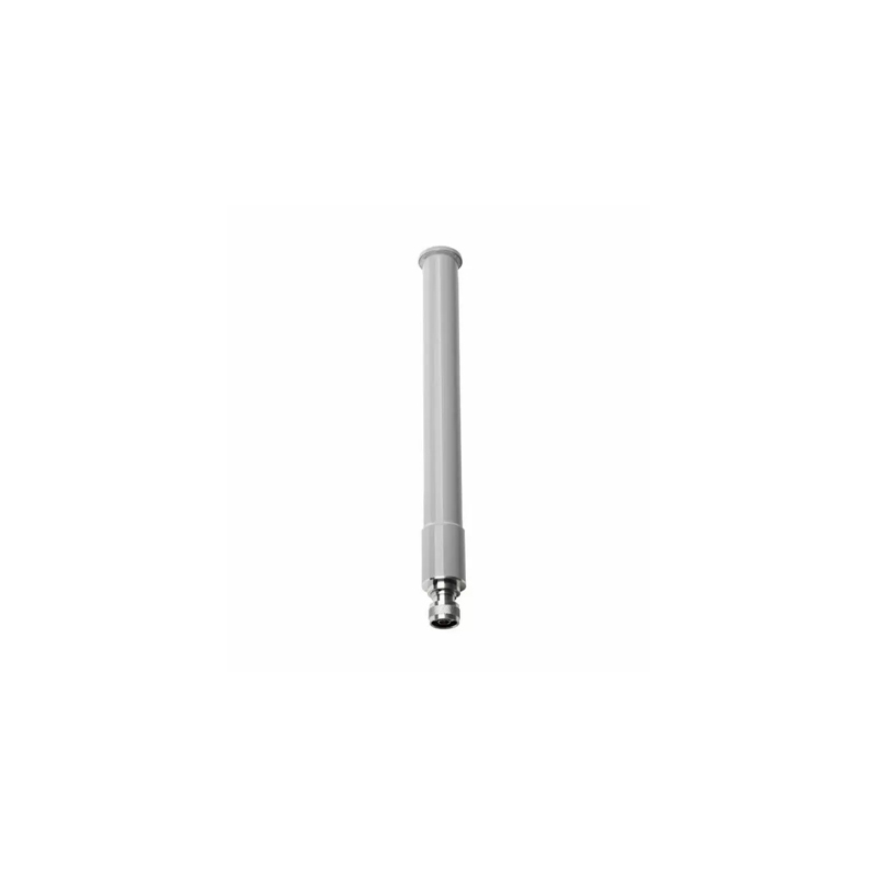
Cisco AIR-ANT2547VG-N Aironet dual-band 2.4 GHz 4 dBi and 5 GHz 7 dBi Omnidirectional N-type Connector Antenna
Product Code | AIR-ANT2547VG-N |
Enclosure Color | Gray |
Antenna Type | Omni-directional collinear array |
Operational Frequency Ranges | 2400–2483 MHz |
Nominal Input Impedance* | 50 Ohms |
Diameter | 1.25 in. (3.18 cm) |
Length | 11.1 in. (28.2 cm) |
Weight | 6.0 oz. (170.0 g) |

Antenna Part Numbers | Radome Color |
White | |
Gray | |
AIR-ANT2547V-N-HZ | White, Hazardous Locations |
This antenna is designed for use with the Cisco Aironet Outdoor Access Points.
Warning: Do not locate the antenna near overhead power lines or other electric light or power circuits, or where it can come into contact with such circuits. When installing the antenna, take extreme care not to come into contact with such circuits, as they may cause serious injury or death. For proper installation and grounding of the antenna, please refer to national and local codes (e.g. U.S.: NFPA 70, National Electrical Code, Article 810, Canada: Canadian Electrical Code, Section 54). Statement 280
For your safety, read and follow these safety precautions:
1. Before you install an antenna, contact your Cisco account representative to explain which mounting method to use for the size and type of antenna that you are about to install.
2. Find someone to help you—installing an antenna is often a two-person job.
3. Select your installation site with safety, as well as performance, in mind. Remember that electric power lines and phone lines look alike. For your safety, assume that any overhead line can kill you.
4. Contact your electric power company. Tell them your plans and ask them to come look at your proposed installation.
5. Plan your installation carefully and completely before you begin. Each person involved in an installation should be assigned to a specific task and should know what to do and when to do it. One person should be in charge of the operation to issue instructions and watch for signs of trouble.
6. When installing your antenna, follow these guidelines:
a. Do not use a metal ladder.
b. Do not work on a wet or windy day.
c. Do dress properly—wear shoes with rubber soles and heels, rubber gloves, and a long-sleeved shirt or jacket.
7. If the assembly starts to drop, move away from it and let it fall. Because the antenna, mast, cable, and metal guy wires are all excellent conductors of electrical current, even the slightest touch of any of these parts to a power line completes an electrical path through the antenna and the installer.
8. If any part of the antenna system should come in contact with a power line, do not touch it or try to remove it yourself. Call your local power company to have it removed safely.
9. If an accident should occur with the power lines, call for qualified emergency help immediately.
The antenna is designed to connect to a dedicated antenna port on the access point. No special tools are required to install the antenna.
The antenna is resistant to the full range of outdoor environments. After the antenna is attached to the access point, seal the connections to prevent moisture and other weathering elements from affecting performance. Cisco recommends using a coax seal (such as CoaxSeal) for outdoor connections. Silicone sealant or electrical tape are not recommended for sealing outdoor connections.
The antenna is designed to create an omni-directional broadcast pattern. To achieve this pattern, the access point should be mounted clear of any obstructions to the sides of the radiating element. If the mounting location is on the side of a building or tower, the antenna pattern is degraded on the building or tower side.
Generally, the higher an antenna is above the ground, the better it performs. A practice is to install your antenna about 5 to 10 ft (1.5 to 3 m) above the roof line and away from all power lines and obstructions.
No tools are required to mount the antenna to the access point. However, you may need a ¾-in. (19 mm) open end or combination wrench (or adjustable wrench) to remove the antenna port covers.
For information about tools required to mount the access point, see the appropriate access point documentation.
To connect the antenna to the access point:
1. If necessary, remove the antenna port cover.
2. Align the antenna’s N-type connector with the appropriate antenna port..
3. Gently push the antenna into the port..
4. Hand tighten the antenna to the port using the metal knurled ring only.
Warning: Do not use the plastic body to tighten. This may damage the antenna.
Do you have any question about the AIR-ANT2547VG-N?
Contact us now via [email protected].
Antenna type | Omni-directional colinear array |
Operating frequency range | 2400–2483 MHz; 5150–5875 MHz |
2:1 VSWR bandwidth | 2400–2483 MHz; 5150–5875 MHz |
Nominal input impedance | 50 Ohms |
Gain (2400–2483 MHz) | 4-dBi |
Gain (5250–5875 MHz) | 7-dBi |
Polarization | Linear |
E-plane 3-dB beamwidth | 2.4 GHz: 30° for5 GHz 14° |
H-plane 3-dB bandwidth | Omni-directional |
Length | 11.1 in. (28.2 cm) |
Diameter | 1.25 in. (3.17 cm) |
Weight | 6.0 oz. (170.0 g) |
Connector type | N-Male |
Mounting | To mast mount the antenna you must purchase the U-bolt bracket from a third party |
Operating temperature | -40–185°F (-40–85°C) |
Water/Foreign Body Ingress | IP66, IP67 |
Wind rating | 100 mph (161 kph) operational165 mph (265 kph) survival |
What is Guaranteed.
After receiving your order, take a full month to try it out. If you find quality is not good , we'll take it back and refund your money. Your complete satisfaction is GUARANTEED or your money back. That's guaranteed.
After your order items which are available. We will use most fast delivery way to global countries. Normally we will ship out cargos during 3 -5 days. And international delivery will take about 3- 10 days according to your location.
Service Never Ends.
Hardwares Warrany Time:
Original New Sealed Hardware: 3 Years
Refurbished/Used Original Devices: 1 Year
After warranty time, you also can contact us to return back for repair service. Everything you purchase from HI-NETWORK.COM. We will offer lifetime online service support for your any possible questions.
Register Email now for Weekly Promotion Stock
100% free, Unsubscribe any time!
Add 1: Room 605 6/F FA YUEN Commercial Building, 75-77 FA YUEN Street, Mongkok KL, HongKong Add 2: Room 405, Building E, MeiDu Building, Gong Shu District, Hangzhou City, Zhejiang Province, China
Whatsapp/Tel: +8618057156223 Tel: 0086 571 86729517 Tel in HK: 00852 66181601
Email: [email protected]
 English
 Pусский
 Français
 Español
 Português