Register now for better personalized quote!

| Detail: | Cisco AIR-ANT2566P4W-R 2.4 GHz 6 dBi/5 GHz 6 dBi Directional Ant., 4-port, RP-TNC |
| Model: | AIR-ANT2566P4W-R |
| Condition: | Factory Sealed New, In stock |
| Related: | |
| Warranty: |
 1 Year-Warranty
 100% Money-back
 Free After-Sales Service
|
| Shipping: |
Air Shipping to
United States
, Most Customers Receive during 5-7 Days
?
If you finish the payment today,
your order will arrive within the estimated delivery time. |
| Ships to:
2.1
|
2-7 Days
US$
|
| Payment: |
More
|
(Note: Cisco discount and Stock always changed, we will try most effort to follow it but can not ensure every web was changed accordingly. So Our Products Service will contact you after order if meet such special condition.)
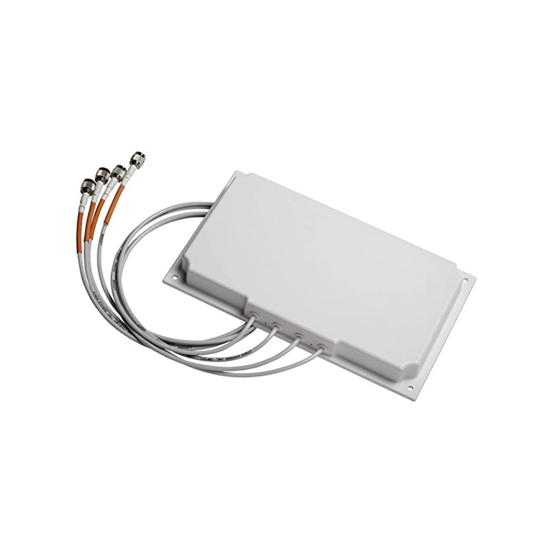
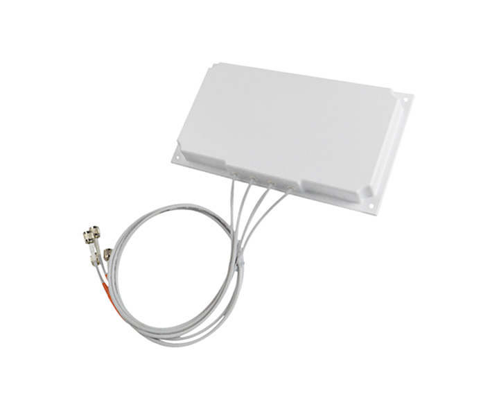
Antennas - Dual Band - Cisco AIR-ANT2566P4W-R , 2.4 GHz 6 dBi/5 GHz 6 dBi Directional Ant., 4-port, RP-TNC
Product Code | AIR- ANT2566P4W-R |
Antenna Type | 4-element dual-band MIMO |
Operational Frequency Ranges | 2400–2484 MHz |
Cable length and type | 3 ft. (91.4 cm) plenum rated |
Connector | RP-TNC |
Length | 6.3 in. (16 cm) |
Width | 11 in. (27.9 cm) |
Depth | 1.2 in. (3.05 cm) |
Weight | 1.4 lbs |

This antenna is designed for indoor and outdoor use with any Cisco Aironet access point that requires four (4) dual-band antennas. The Self Identifying Antenna model AIR-ANT2566P4W-RS= is supported only on Cisco Catalyst 9800 Series Wireless Controllers running an IOS-XE 17.4.1 release or a later release. This antenna model is not supported on Cisco AireOS Wireless Controllers.
Warning: Installation of this antenna near power lines is dangerous. For your safety, follow the installation directions.
Each year hundreds of people are killed or injured when attempting to install an antenna. In many of these cases, the victim was aware of the danger of electrocution but did not take adequate steps to avoid the hazard.
For your safety, and to help you achieve a good installation, please read and follow these safety precautions. They may save your life!
1. If you are installing an antenna for the first time, for your own safety as well as others, seek professional assistance. Your Cisco sales representative can explain which mounting method to use for the size and type antenna you are about to install.
2. Select your installation site with safety as well as performance in mind. Remember: electric power lines and phone lines look alike. For your safety, assume that any overhead line can kill you.
3. Call your electric power company. Tell them your plans and ask them to come look at your proposed installation. This is a small inconvenience considering your life is at stake..
4. Plan your installation carefully and completely before you begin. Each person involved in an installation should be assigned to a specific task and should know what to do and when to do it. One person should be in charge of the operation to issue instructions and watch for signs of trouble.
5. When installing your antenna, follow these guidelines:
a. Do not use a metal ladder.
b. Do not work on a wet or windy day.
c. Do dress properly—wear shoes with rubber soles and heels, rubber gloves, and a long-sleeved shirt or jacket.
6. If the assembly starts to drop, move away from it and let it fall. Because the antenna, mast, cable, and metal guy wires are all excellent conductors of electrical current, even the slightest touch of any of these parts to a power line completes an electrical path through the antenna and the installer.
7. If any part of the antenna system should come in contact with a power line, do not touch it or try to remove it yourself. Call your local power company to have it removed safely.
8. If an accident should occur with the power lines, call for qualified emergency help immediately.
Antennas transmit and receive radio signals which are susceptible to RF obstructions and common sources of interference that can reduce throughput and range of the device to which they are connected. Follow these guidelines to ensure the best possible performance:
·Install the antenna vertically and mount it with the cables pointing towards the ground.
·Keep the antenna away from metal obstructions such as heating and air-conditioning ducts, large ceiling trusses, building superstructures, and major power cabling runs.
If necessary, use a rigid conduit to lower the antenna away from these obstructions.
·The density of the materials used in a building’s construction determines the number of walls the signal can pass through and still maintain adequate signal strength. Consider the following before choosing the location for your antenna:
– Signals penetrate paper and vinyl walls with little change to signal strength.
– Signals penetrate only one or two solid and pre-cast concrete walls without degrading signal strength.
– Signals penetrate three or four concrete and wood block walls without degrading signal strength.
– Signals penetrate five or six walls constructed of drywall or wood without degrading signal strength.
– Signals will likely reflect off a thick metal wall and may not penetrate it at all.
– Signals will likely reflect off a chain link fence or wire mesh spaced between 1 and 1 1/2 in. (2.5 and 3.8 cm). The fence acts as a harmonic reflector that blocks the signal. ·Install the antenna away from microwave ovens and 2-GHz cordless phones. These products can cause signal interference because they operate in the same frequency range as the device to which your antenna is connected.
The antenna should be mounted clear of any obstructions to the sides of the radiating elements. Generally, the higher an antenna is above the floor, the better it performs. If possible, find a mounting place directly above your wireless device to ensure the lead-in cable can be as short as possible.
A mounting installation kit is shipped with the antenna and consists of the following hardware:
·Four#8 x 1¼ screws ·Four#8 plastic anchors
·Four end caps
You may need the following tools and equipment, which are not provided.
·A Phillips screwdriver
·A drill ·A#29 (0.136-in. (s.45 mm)) drill bit (for drywall installation, other surfaces may require a different size).
·A pencil
·A small mallet or hammer
Follow these steps to mount your antenna on a vertical surface. This procedure describes mounting the antenna on a drywall surface. If you are mounting the antenna on any other type of surface, your procedure may vary slightly.
Step 1 Determine the location where you will mount the antenna.
Step 2 Use the antenna as a template to mark the location of the four mounting holes.
Step 3 Use a drill and#29 drill bit to drill four holes at the locations you marked in Step 2.
Step 4 Start a plastic anchor into each hole.
Step 5 Use a mallet or small hammer to seat the anchors into the wall.
Step 6 Align the antenna’s mounting holes with the anchors.
Step 7 Start a#8 x 1¼ screw into each antenna mounting hole.
Step 8 Use a Phillips screwdriver to secure the antenna to the wall. Do not overtighten.
Step 9 Install the end caps into the antenna mounting holes.
Step 10 Remove the yellow outdoor installation warning label from the antenna radome.
Do you have any question about the AIR-ANT2566P4W-R?
Contact us now via [email protected].
Antenna type | 4-element dual-band MIMO |
Operating frequency range | 2400 to 2484 MHz |
5150–5850 MHz | |
VSWR | 2:1 or less |
Gain | 6 dBi in both bands |
Polarization | Linear, vertical |
Azimuth Plane 3-dB Beamwidth | 2.4 GHz band: 105° |
5 GHz band: 110° | |
Elevation Plane 3-dB Beamwidth | 2.4 GHz band: 65° |
5 GHz band: 55° | |
Length | 6.3 in. (16 cm) |
Width | 11 in. (27.9 cm) |
Depth | 1.2 in. (3.05 cm) |
Weight | 1.4 lbs |
Cable length and type | 3 ft. (91.4 cm) plenum rated |
Connector | RP-TNC |
Environment | Indoor/outdoor |
Water/Foreign Body Ingress | IP54 |
Operating temperature range | -40° to 158° F |
-40° to 70° C |
What is Guaranteed.
After receiving your order, take a full month to try it out. If you find quality is not good , we'll take it back and refund your money. Your complete satisfaction is GUARANTEED or your money back. That's guaranteed.
After your order items which are available. We will use most fast delivery way to global countries. Normally we will ship out cargos during 3 -5 days. And international delivery will take about 3- 10 days according to your location.
Service Never Ends.
Hardwares Warrany Time:
Original New Sealed Hardware: 3 Years
Refurbished/Used Original Devices: 1 Year
After warranty time, you also can contact us to return back for repair service. Everything you purchase from HI-NETWORK.COM. We will offer lifetime online service support for your any possible questions.
Register Email now for Weekly Promotion Stock
100% free, Unsubscribe any time!
Add 1: Room 605 6/F FA YUEN Commercial Building, 75-77 FA YUEN Street, Mongkok KL, HongKong Add 2: Room 405, Building E, MeiDu Building, Gong Shu District, Hangzhou City, Zhejiang Province, China
Whatsapp/Tel: +8618057156223 Tel: 0086 571 86729517 Tel in HK: 00852 66181601
Email: [email protected]
 English
 Pусский
 Français
 Español
 Português